Site Layout
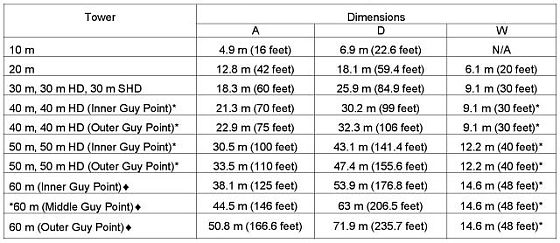
The tower site should be flat and free of obstacles (trees, bushes, buildings, etc.) within the perimeter of the tower anchors and the longest dimension of the tower. The figure and table below give the dimensions of the tower layouts for the 20m and 30m towers.

Anchors
Before the tower is installed, the soil type should be determined to assure that the correct anchors are used.
Because anchor requirements are site specific, it remains the responsibility
of the Lessee and the CSU ALP to determine anchor requirements. If you are not sure what is required, seek
professional guidance. Local utility companies can often provide useful information regarding
anchoring used in the site area.
The choice of anchors must take into consideration soil type, maximum winds to be experienced,
icing or other weather that may affect the tower, and a safety factor suitable for the location and to
meet any legal requirements. Soil classes are defined in the table below:
Class |
Common Soil Types |
Geological Soil Classification |
3 |
Dense clays, sands and gravel; hard silts and clays |
Glacial till; weathered shales, schist, gneiss and siltstone |
4 |
Medium dense sandy gravel; very stiff to hard silts and clays |
Glacial till; hardpan; marls |
5 |
Medium dense coarse sand and sandy gravels; stiff to very stiff silts and clays |
Saprolites, residual soils |
6 |
Loose to medium dense fine to coarse sand; firm to stiff clays and silts |
Dense hydraulic fill; compacted fill; residual soils |
7 |
Loose fine sand; Alluvium; loess; soil-firm clays; varied clays; fill |
Flood plain soils; lake clays; adobe; gumbo; fill |
Considerations include but are not limited to: tornadoes, hurricanes or typhoons, locations where
very high winds are expected, periodic soaking of the soil which may shift or become undermined,
and icing events.
The table below lists the maximum anchor loads for each tower at the maximum rated wind speed. Anchors
must be placed at the correct angle to provide specified holding power and to prevent shifting of the
anchors under load.
There are four types of anchors available: screw-in, arrowhead, rock anchors, and concrete anchors made from screw-in anchors.
Screw-In Anchors
Screw-in anchors are the most commonly used anchors for normal clay soils without rocks. They
are installed by hand, using a cross bar to screw them into the earth like a corkscrew. Screw-in anchors can also used to provide the anchoring rod and eye for site-built anchors, such as concrete.
Specifications for Screw-In Anchors |
These anchors are not suitable for soils denser than Class 5 |
Helix diameter |
6 inches |
Length Overall |
66 inches |
Rod diameter |
0.75 inches |
Material |
Galvanized steel |
Holding Power |
Class 5 soils |
6,500 pounds |
Class 6 soils |
5,000 pounds |
Class 7 soils |
2,500 pounds |
In Class 7 soils, it is advisable to place anchors deep enough to penetrate to underlying Class 5
or 6 soil.
To install screw-in anchors, screw the anchor into the ground by placing a stout bar through the eye of the anchor, and
rotating clockwise. It is sometimes helpful to start the anchor into the ground straight down for
the first turn, then push it down to the correct angle and complete the installation. Continue screwing the anchor into the ground until about 6 inches of the anchor rod remain
above the ground.
If the anchor cannot be installed due to rocks in the soil, or other obstacles, try placing the anchor
as much as 3 feet from its ideal position to avoid the obstacle, or replace the screw-in
anchor with the correct anchor for the soil. If necessary, a hole can be dug for the screw-in anchor to the proper installed depth, the anchor
placed in the hole, and the hole back-filled. The earth must be tamped onto the anchor hard
while back filling. The holding power of an anchor placed this way will not be as great as an
anchor screwed into undisturbed soil.
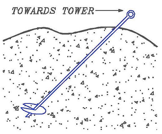
Note: Unlike a tent stake, screw-in anchors are installed in line with the pull of the guy wires from
the tower. It is important to install the anchor at an angle of 45 degrees and pointing towards the tower so the eye of the anchor is toward the
tower and the helix screws in away from the tower. If the anchor is incorrectly installed straight
into the ground, the load will bend the rod and pull it through the ground, allowing the guys to go
slack.
Arrowhead Anchors
Arrowhead anchors can penetrate stiff and rocky soils because the triangular design tends
to thread its way between obstacles such as rocks, which can prevent successful installation of screw-in anchors. Arrowhead anchors are driven into the ground with a hardened steel drive rod with a fence driver, a sledge hammer, or a power jackhammer. Once in the ground, upward force on the attached cable rotates the anchor perpendicular to the cable for maximum holding power.
Specifications for Arrowhead Anchors |
Length Overall |
48 inches |
Arrowhead Length |
8 inches |
Rod diameter |
0.75 inches |
Materials |
0.25 inches galvanized (7x19) steel cable; breaking strength - 4,200 pounds; with malleable iron head. |
Holding Power |
Class 3 soils |
4,200 pounds |
Class 4 soils |
3,000 pounds |
Class 5 soils |
2,000 pounds |
Class 6 soils |
1,200 pounds |
Class 7 soils |
600 pounds |
Arrowhead anchors are designed for all soils but are especially effective in rocky soils.
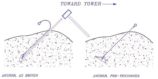
The arrowhead anchor is driven into the soil with a special drive rod. The rod is removed leaving the anchor in the ground. Then the anchor must be pre-tensioned which will cause the anchor to rotate in the ground developing its full holding potential.
Like screw-in anchors, the arrowhead anchor must be placed so the force from the guy wires
pulls directly on the anchor. Drive the arrowhead anchor away from the tower at an angle of 45 degrees into the
ground and pointing towards the tower.
To install the anchor, place the drive rod over the anchor’s shank. Drive the anchor into the soil
using a sledgehammer, fence post driver, or power jackhammer, until the cable eye attached to
the anchor is 2 inches to 4 inches above the surface of the ground.
After the anchor is driven, remove the drive rod, leaving the anchor in the ground. The anchor
must now be pre-tensioned by applying strain to the cable. This can be done using a lever,
come-along, jack, or winch. Pre-tensioning causes the anchor to rotate in the ground developing
its full holding power. The pull distance will be approximately the length of the anchor head, (8 inches). The tension should become significantly higher as the pre-tensioning is complete.
The anchor must be properly pre-tensioned before attaching the tower guys. If it is not, the tower guy tension will turn the anchor later, resulting in significant slack in the tower guys, and possible tower failure.
Note: It is important to drive the anchor at an angle. If the anchor is incorrectly installed straight
into the ground, the load will result in the anchor cable cutting through the ground until the angle
is correct, resulting in significant slack in the tower guys, and possible tower failure.
Rock Anchors
Rock anchors are placed into solid rock, when anchoring to either bare rock, or thin soils with
solid rock near the surface. They are constructed of a threaded rod with integral eye, and two
opposing wedge halves. The anchor is placed in a hole pre-drilled in the rock. Twisting the eye
of the anchor forces the wedges against the sides of the hole, locking the anchor in place. Load
actually increases the wedging force, developing holding power equal to the full tensile strength
of the rod.
Specifications for Rock Anchors |
Holding Power |
20,000 pounds |
Rod Length Overall |
15 inches, 30 inches, or 53 inches |
Anchor diameter |
1.75 inches as supplied, 2.375 inches max. expanded |
Rod diameter |
0.75 inches |
Materials |
Malleable iron, dipped in rust-resisting black paint |
Required Hole Size |
2 inches diameter (nominal) |
Use Rock Drill Size |
2 inches diameter |
Rock anchors are used when anchoring to either bare rock or thin soils with solid rock near the
surface.
Like any anchor, rock anchors must be placed so the force from the guy wires pulls directly on the
anchor. Drill the hole for the anchor away from the tower at an angle into the ground.
Note: It is important to install the anchor at an angle of 45 degrees and towards the tower. If the anchor is incorrectly installed straight
into the ground, the load will bend the rod until the angle is correct, resulting in significant slack in
the tower guys and possible tower failure.
To install the anchor, a hole must be pre-drilled in the rock by hand or power tool. The hole must
be 2 inches in diameter, and the walls of the hole should be smooth in the area that the
anchor will wedge.
Place the anchor in the hole. Using a bar through the eye of the anchor, turn clockwise to tighten.
The anchor will expand and wedge into the hole.
After placing the anchor, fill the hole around the rod with expanding cement grout. One brand is "Rocktite” made by Hartline Products Co, Cleveland, OH, USA (telephone: +216 291 2303).
Always grout rock anchors to prevent water from collecting and freezing in the drilled hole.
Grouting also increases the anchor’s holding strength.
Concrete Anchors
The most common alternative anchoring system is to place site-built concrete anchors. A hole is
excavated at the anchor position. Reinforcing steel is placed in the hole. A screw-in anchor is
often tied into the reinforcing steel to provide a rod and eye above ground to attach the guys.
Concrete is poured in place to form the anchoring mass, and the hole is then back-filled.
Guidelines for concrete anchors:
- The anchors must be placed carefully to provide anchor points at the proper locations for the tower.
- The holding power of concrete anchors is essentially due to their weight. The weight of concrete placed must exceed the required anchor holding force.
- Concrete anchors still depend on the soil to prevent the concrete mass from shifting toward the tower under load.
|