

Phone: (970)491-8564
Fax: (970)491-8671
Email: john.d.williams@colostate.edu
Hall Effect Thrusters
A Hall Effect Thruser (HET) is a type of electric propulsion device that uses both magnetic and electric fields. A radial magnetic field is used to cycle electrons within a cylindrical dicharge channel; these electrons bombard neutral propellant to create ions. An an axial electric field is used to accelerate ions to produce thrust. Electrons are fed to the discharge plasma by a cathode, traditionally placed external to the channel, alternatively placed on-axis if space allows.
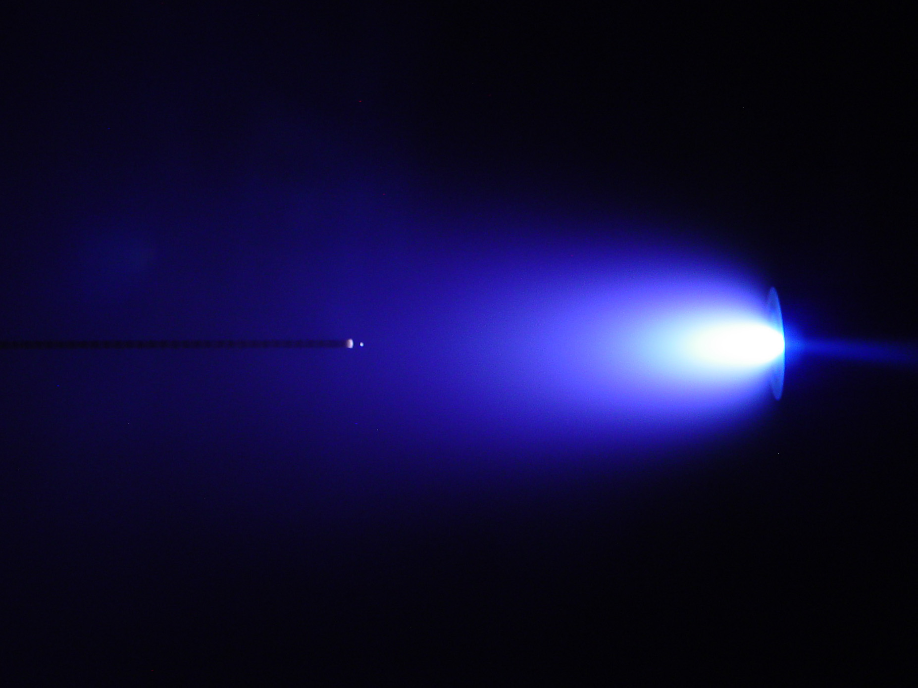
The CSU 1.5 kW Hall effect thruster can be operated over a power range of 0.5 - 2.5 kW. It incorporates a center mounted heaterless electride hollow cathode for optimum performance and minimum plume divergence. At 1.5 kW, the thruster is capable of >2,000 seconds Isp and >60% efficiency.
Operating with Krypton:

Operating with Xenon:

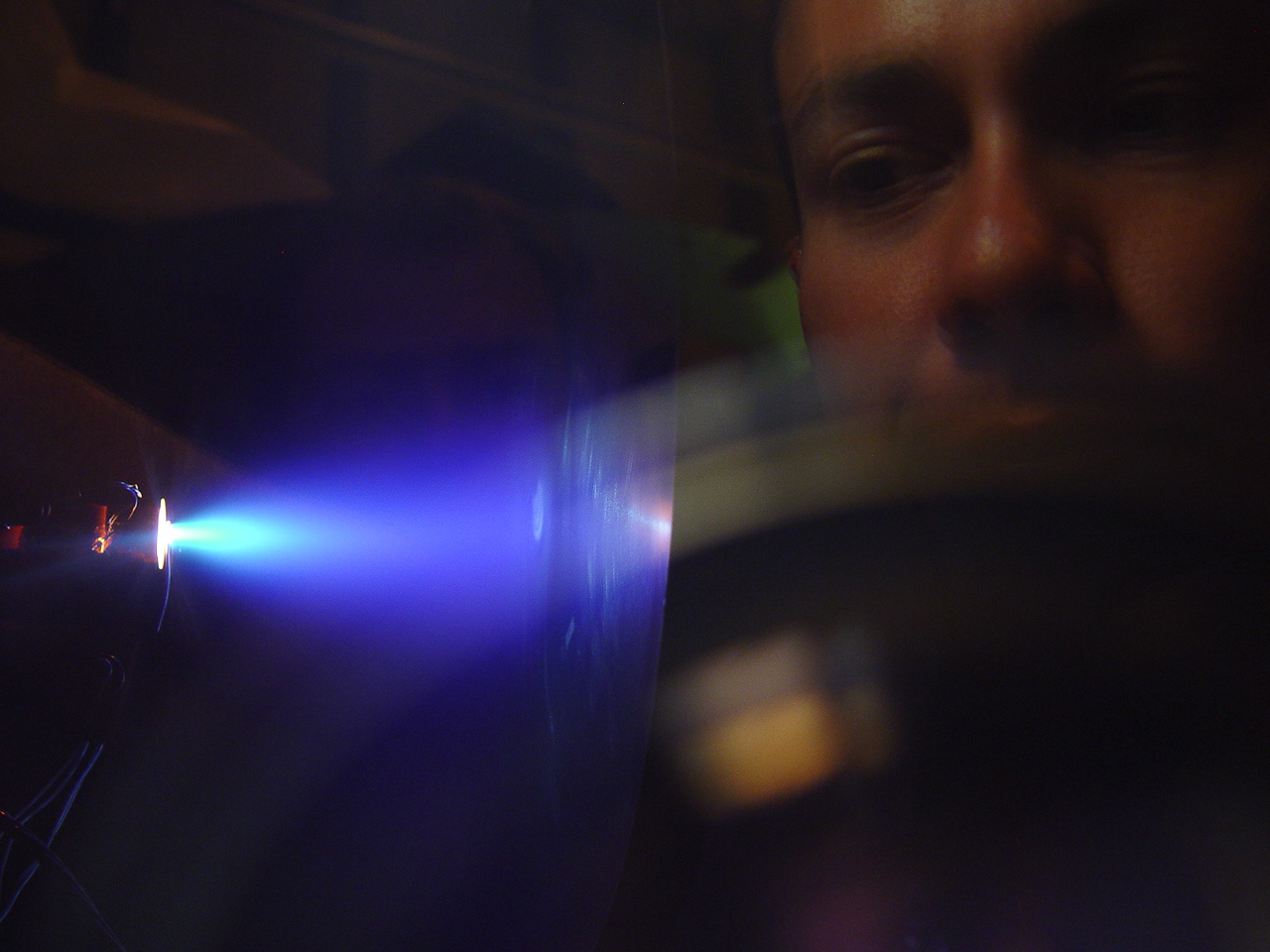
3D-Printed Long Life Miniature Hall Thruster with Center Mounted Heaterless Cathode
A miniature Hall thruster having 3D-printed (i.e., additive manufacturing) components, magnetic shielding of the walls from ionized plasma, an integrated discharge channel and gas distributor arrangement, and a heaterless hollow cathode mounted internally to the thruster has been developed at CSU. The design offers many advantages over existing state-of-the-art Hall thrusters of similar power levels, including: half the mass of those thrusters, significantly longer life time, lower cost, lower part count, higher performance, and the ability to be continuously throttleable.

3D Printed Long Life Miniature 20-400 W HET next to a 1.5 kW HET. The miniature HET is ideal for CubeSats and microsatellites with the ability to operate efficiently using a range of propellants including xenon and iodine using its electride hollow cathode.
The miniature thruster has a power range of 20 to 400 Watts. This wide power range is achieved through the thruster's ability to be continuously throttleable. This means the thruster-cathode system can be turned on and left on for a nearly arbitrary time and then left off for another nearly arbitrary time. Specifically, 0.1 s < Time On < many 1000's hr and 0 < Time Off < many 1000's hr. The thruster is currently the smallest magnetically shielded Hall thruster in the world and is the smallest Hall thruster to incorporate a center mounted hollow cathode. It is also the first one to incorporate 3-D printed components.


Electride Cathodes
We are researching the use of the electride form of 12CaO7Al2O3 as an electron emitting cathode. Ion and Hall thrusters use cathodes to provide electrons to sustain plasma discharges and neutralize ion beams. Traditional electron emitters include barium-impregnated porous tungsten, Lanthanum hexaboride (Lab6), and cerium hexaboride (CeB6). A key property of an electron emitting material is its work function; C12A7 electride has been found to have a lower work function than the traditional materials, which may lead to lower operating temperatures and increased resistance to contamination.
An electride cathode, shown with a Langmuir probe placed in the cathode's plasma plume:
Bare Electrodynamic Tethers Project (BETs)

Hollow Cathodes
In space applications, hollow cathodes are used in electrostatic propulsion devices, especially in ion thrusters and Hall thrusters, to provide electrons to produce and sustain the plasma. The cathode assembly consists of the cathode tube, low work function insert, heater, and keeper. An internal plasma is generated by flowing propellant through the cathode and heating the low work function insert to thermionically emit electrons off the surface. The electrons collide with the neutral atoms to ionize a portion of the propellant to create the plasma. The keeper is biased positive of the cathode to draw the electrons out of the cathode and into the main discharge chamber.

Hollow cathode diagram. Electrons are emitted from the insert to produce the plasma.


Hollow cathode, insert, and front view with keeper.
CSU has operated a multi-insert hollow cathode up to 100A of emission:

One past focus of research at CSU was investigating and characterizing the plasma produced near the hollow cathode. This research was important with respect to thruster life tests, which have shown erosion to the hollow cathode, keeper, and ion optics, presumably caused by ions produced in the surrounding plasma. The erosion has the potential to limit the life of the thruster, especially for long duration missions. Researchers have proposed theories as to how plasma ions are produced that would erode the cathode. Some ideas are potential hills, magnetohydrodynamic effects, charge exchange energy gains, multiply charged ions, and turbulent oscillating plasmas.

Discharge chamber schematic.

CSU plasma discharge chamber.
In experimental work done recently at CSU, hollow cathodes have been studied in an environment similar to that of an actual ion thruster. A discharge chamber has been setup with similar operating conditions to the NSTAR ion thruster. Various diagnostic tools, such as electrostatic analyzers, ExB probes, retarding potential analyzers, emissive probes, and Langmuir probes are being used to study the plasma.

Fig. 3a CSU discharge chamber. The cathode is located near the bright plasma spot.

Fig. 3b Sample test setup to probe the discharge chamber plasma.
Ion Optics
The ion optics, or grids, are used to accelerate ions from the discharge chamber to produce thrust. Grid lifetime is limited by erosion that occurs due to impinging charge exchange ions. The speed of the expelled ions depends on the net voltage difference between the ion thruster and the surrounding beam plasma. The amount of extracted current, and thrust, depends on the plasma density within the discharge chamber as well as the voltage difference between the grids.
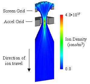
|
Ion Beam Animation Discharge chamber ions drift until they fall downstream of the sheath, where they start to feel the pull of the negative accel grid.
|
Over time, a "pit and groove" erosion pattern develops on the downstream side of the accel (accelerator) grid. Eventually, the grooves will wear entirely through the accel grid thickness, causing a section of the grid to dislodge, possibly resulting in a short between the grids. Alternatively, thruster failure can occur when electrons are allowed to backstream through the grids into the discharge chamber, causing heating. The accel grid is held negative to prevent this, but over time the resistance to backstreaming is reduced as the accel grid hole enlarges and the accel grid thins.

One goal of ion optics research is to predict, and improve, grid lifetime. Two ion optics codes have been developed at CSU, the igx and ffx codes. The igx code is a 3-D cylindrical code that analyzes typical grid sets with hexagonal aperture layout patterns. The ffx code is also 3-D, but analyzes a rectangular prism volume that can be tailored to the aperture layout pattern.

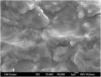
Sputtering & Erosion

Cone formation during sputtering.
Sputter erosion of surfaces is of great importance for electric propulsion (EP) thrusters and spacecraft employing such thrusters. Sputtering has been identified as a major concern in 80% of the possible failure modes of an electrostatic thruster, and sputtering of spacecraft surfaces have resulted in property modification of surface materials. Additionally, deposition of sputtered products onto other spacecraft surfaces can result in modification of surface material properties, or contamination. In order to model the effects of sputter erosion it is critical to have detailed fundamental sputter erosion data.
Typically, the data used for modeling of EP lifetime (sputter erosion) and/or erosion of spacecraft surface materials is expressed in terms of the total sputter yield, Y, (i.e. the number of sputtered atoms per incident ion) and provides no information regarding the spatial distribution of the sputtered particles. A cosine distribution of sputtered particles is often assumed regardless of the angle of incidence of the sputtering atoms or molecules. However, angularly resolved (differential sputter yield) measurements have shown that the assumption of a cosine distribution is inappropriate for low energy incident ions, especially for non-normal angles of incidence.
Differential yield distributions are useful, for example, in determining thruster locations where sputtered material can deposit. Such deposits can lead to build-up and flaking and may cause electrical or contamination problems. Thus, the differential yield data are of paramount importance when determining where equipment sensitive to surface contamination (e.g. optical devices and photovoltaics) can be located. Also, when designing vacuum chamber beam dumps the differential yield data could be used to determine the optimum orientation of surfaces that minimizes deposition of back-sputtered beam dump material onto EP test devices, thereby considerably improving the quality of wear test measurements. Accordingly, differential yield data can be used to significantly increase the accuracy of ion optics wear models.


Spector research system set up with weight loss wear samples.
Hydroxyapatite Thin Films
One of the leading causes of failures in total joint replacements is loosening of the joint stem. A loose implant can result in pain, bone death, or complete loss of joint function. This phenomenon is usually initiated by a lack of bonding between the implant surface and the natural tissue, combined with the normal loading demands to which the joint is subjected. In some procedures, bone cement is used to fill the voids between the bone and the implant surface in an effort to better secure the implant. However, use of bone cement may result in formation of debris that could affect the healing process. More recently, focus has shifted to cementless joint replacements which utilize a texturized or coated titanium surface to encourage osseointegration (bone in-growth). The focus of modifying these implants is to create more biomimetic interfaces on which the bone cells can adhere, proliferate and deposit new bone.


Hydroxyapatite (Ca5(PO4)3OH) is a naturally occurring mineral that comprises 70% of healthy bone. By coating implants with a thin film of this material, the body is more willing to accept the implant and integrate it with healthy bone. Our research focuses on how to deposit and texturize the hydroxyapatite films in a way that maximizes osteoblast (bone cell) response.
Emissive Membrane Ion Thruster
An evolving technology that holds great potential for ion thruster applications is that associated with solid-state ionic conductors. Applications of this technology in everyday life are growing rapidly as a very wide range of new devices evolves. Presently solid-state ionic conductors are the key elements in the ubiquitous oxygen sensors used in automobile exhaust systems, in lithium ion batteries, in solid oxide fuel cells, in electrochromic windows and in some superconductors. They are a potentially attractive element for ion thrusters because they enable the production and delivery of ions to sites where they can be extracted into a beam without the complications of a plasma discharge chamber and all of its essential components (from the introduction to The Emissive Membrane Ion Thruster Concept, IEPC 2005-164).

Concept for an Emissive Membrane Ion Thruster.
The use of Emissive Membrane Ion Thrusters enables elimination of discharge chambers, discharge power supplies, and associated components such as magnets and hollow cathodes. This, plus a greatly simplified propellant feed system, will reduce system complexity and cost while enhancing reliability and fault tolerance compared to existing thruster technology. Current concerns with grid shorting due to grid deflection and discharge chamber flakes will also be mitigated greatly thereby enhancing reliability even more.
Compared to state-of-the-art ion thrusters, Emissive Membrane Ion Thrusters can operate at greater beam current densities with greater beam flatness. Because the emissive membrane can be shaped optimally they are well suited to low specific impulse operation.
The Emissive Membrane Ion thruster is fully scalable from nanometer dimensions without degradations in efficiency.